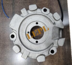
Brake coils are electromagnetic components integrated into AC induction motors used in concrete batching plants, particularly for skip hoist and mixer drives, typically part of a spring-loaded, fail-safe electromagnetic disc brake assembly. These coils generate a magnetic field to engage a friction disc or drum brake, providing fail-safe holding and dynamic stopping for heavy loads.
Brake coils and their assembly are crucial components in the motors used in concrete batching plants, providing an essential fail-safe braking system to ensure safety and precision, particularly in controlling mixers and material skip hoists.
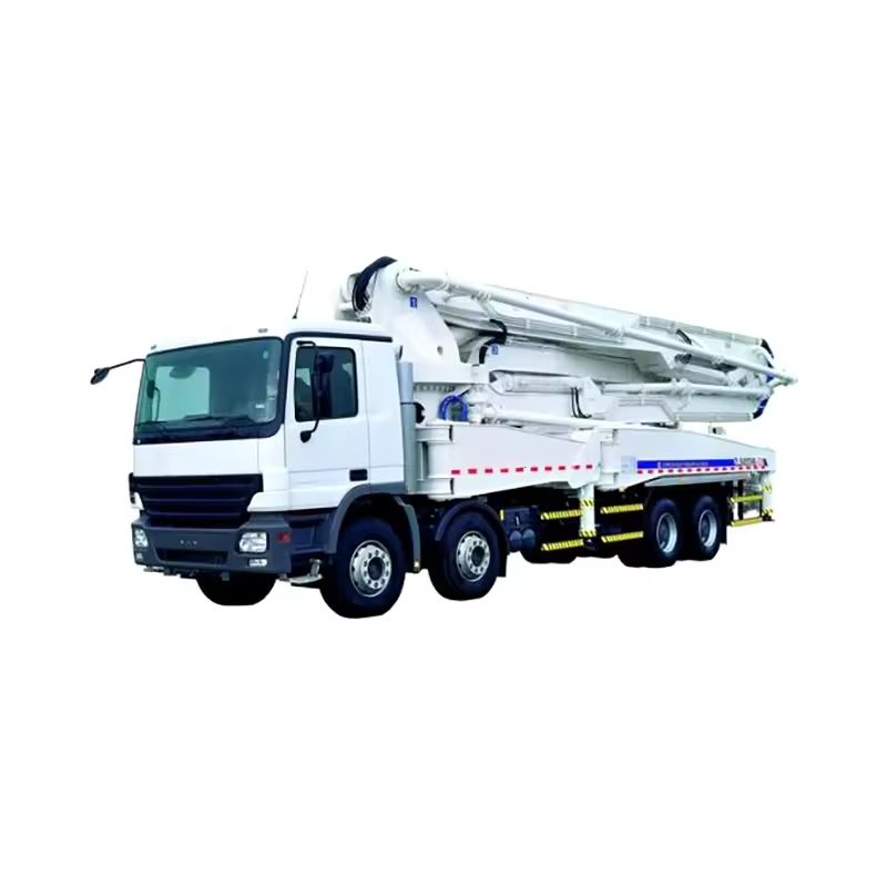
In concrete batching plants, these brakes are attached to the motors (e.g., SEW, Bonfiglioli, Nord) that drive key mechanisms like the mixer or the skip hoist.
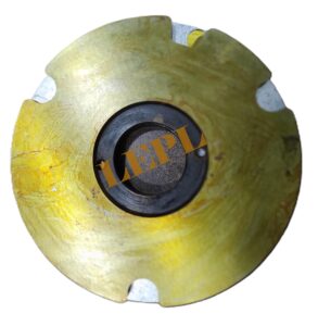
The entire brake assembly generally consists of:
Magnet Coil (Brake Coil): The wire winding (often copper) that generates the magnetic field.
Armature Plate: A movable component attracted by the magnetic field.
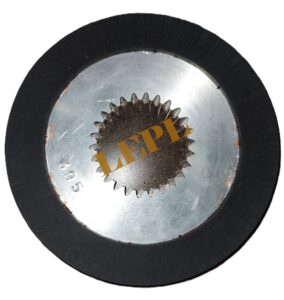
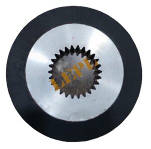
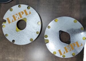
Brake Disc (Rotor): A disc with friction linings splined to the motor shaft.
Compression Springs: Springs that apply the braking force when the coil is de-energized.
Housing/Magnet Body: The fixed part of the brake assembly that holds the coil and springs.
Applications of a brake coil in batching plant motors
- Holding heavy loads safely
The brake coil maintains the mixer or conveyor in a stationary position when the motor is switched off.
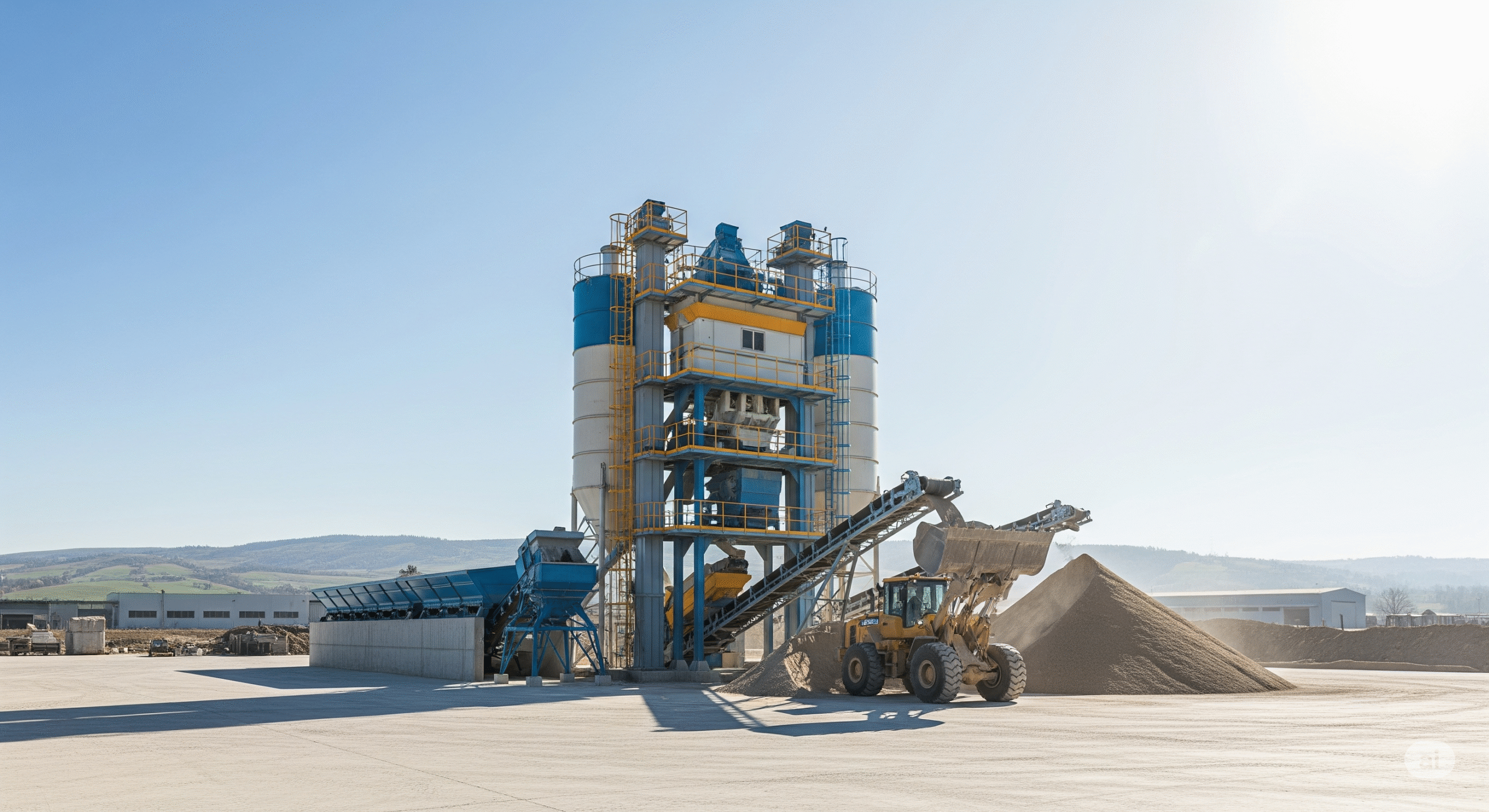
In concrete batching plants, motors drive:
- Skip hoists
- Belt conveyors
- Cement screw conveyors
- Bucket elevators
The brake coil ensures the motor holds the load in position when power is off, preventing:
- Skip buckets from falling
- Conveyors from rolling back
- Cement material backflow
- Fail-safe operation
Brake coils are designed as fail-safe brakes:
Power ON → Brake coil energized → Brake released
Power OFF → Brake coil de-energized → Brake applied
This is critical during:
- Power failures
- Emergency stops
- Electrical faults
It protects equipment, material, and personnel.
- Precise stopping and positioning
Ensure the skip stops exactly at the correct discharge point over the mixer, which is crucial for the batching process.
Batching plants require accurate material dosing. Brake coils help motors:
- Stop instantly
- Avoid overrun of belts or hoists
- Maintain accurate batch weights
This is especially important for aggregate and cement feeding systems.
- Preventing mechanical damage
Without a brake:
- Loads may cause reverse rotation
- Gearboxes and couplings can be damaged
The brake coil helps lock the motor shaft, extending the life of:
- Gear reducers
- Couplings
- Drive shafts
- Improved safety during maintenance
When the brake coil is de-energized:
- The motor shaft is locked
- Moving parts cannot rotate unexpectedly
This allows safer inspection and maintenance of batching plant equipment.
The brake coil in a motor used in a concrete batching plant is essential for:
- Load holding
- Fail-safe braking
- Accurate batching
- Equipment protection
- Operator safety
A motor brake in a batching plant is usually a spring-applied, electrically-released electromagnetic brake.
- Springs apply the brake
- Brake coil releases the brake
Main parts involved
- Brake coil (electromagnet)
- Brake disc / friction plate
- Pressure springs
- Armature plate
- Motor shaft
Step-by-step working
- Motor OFF (no power) → Brake APPLIED
- Brake coil is not energized
- Springs push the armature plate against the brake disc
- Brake disc grips the motor shaft
- Shaft cannot rotate
Example:
If power fails while lifting aggregates in a skip hoist, the bucket stays in position and does not fall.
- Motor ON (power supplied) → Brake RELEASED
- Power is supplied to the brake coil
- The coil creates a magnetic field
- Magnetic force pulls the armature plate away from the brake disc
- Springs are compressed
- Brake disc is released
- Motor shaft rotates freely
Example:
When the skip hoist motor starts, the brake releases first, then the motor lifts the load smoothly.
- Motor STOP command → Brake ENGAGES
- Power to motor and brake coil is switched OFF
- Magnetic field disappears
- Springs immediately push the armature plate back
- Brake disc clamps the shaft
- Motor stops quickly and holds position
This prevents belt overrun or bucket rollback.
Electrical sequence in batching plants
Usually wired so that:
- Brake coil energizes slightly before motor starts
- Brake engages immediately when motor stops
Often done using:
- Contactor auxiliary contacts
- Brake rectifier (for DC brake coils)

Working Principle
The brake assembly operates on an electromagnetic principle and is designed to be "fail-safe" (or spring-applied/power-off brake):
Braking Condition (Power OFF):
- No electrical current flows through the brake coil.
- The compression springs are fully extended, physically pressing the armature plate against the brake disc (rotor).
- Since the brake disc is connected to the motor shaft via a splined hub, the friction force locks the motor shaft, preventing it from rotating. This ensures the load (e.g., a skip bucket or a mixer drum) is immediately held in place if power is lost, hence the "fail-safe" designation.
Released Condition (Power ON):
- Electrical current (usually AC converted to DC via a rectifier) is supplied to the brake coil.
- The coil generates a strong electromagnetic field.
- This magnetic field attracts the armature plate against the spring force, pulling it away from the brake disc.
- The brake disc is thus released, allowing the motor shaft to rotate freely and the machinery to operate.
Key Features of a Brake Coil (Batching Plant Motor)
- Fail-Safe Operation
- Brake is spring-applied
- Brake coil releases the brake only when energized
- On power failure, brake applies automatically
- Prevents load fall (skip hoist, bucket elevator)
- Electromagnetic Working Principle
- Works using electromagnetic attraction
- Coil creates magnetic field to pull armature plate
- No mechanical actuation needed
- Reliable and fast response
- Fast Engagement & Release
- Brake releases before motor starts
- Brake engages immediately when motor stops
- Ensures precise stopping and positioning
- High Holding Torque
- Designed to hold heavy vertical and inclined loads
- Torque rating matched to motor size and application
- Essential for hoists and conveyors
- DC Operation (with Rectifier)
- Most brake coils are DC powered
- AC supply converted to DC using a rectifier
- Smooth, vibration-free operation
- Longer coil life
- Compact & Motor-Mounted Design
- Mounted at the rear of the motor
- Integrated with motor shaft
- Saves space in batching plant layout
- Low Maintenance
- Few moving parts
- No hydraulic or pneumatic systems
- Suitable for dusty concrete plant environments
- Thermal Protection & Insulation
- High-temperature insulation (Class F / H)
- Withstands frequent starts and stops
- Reliable in harsh operating conditions
- Manual Release Option (Optional)
- Hand release lever available in some brakes
- Useful during maintenance or emergency unloading
- Long Service Life
- Wear-resistant friction lining
- Designed for high duty cycles
- Reduced downtime in plant operation
Brake Coil – Typical Specifications (Batching Plant Motor)
- Rated Voltage
- DC Voltage: 24 V DC / 90 V DC / 180 V DC
- AC Input (via rectifier): 230 V AC / 415 V AC
Most batching plants use DC brake coils with rectifiers.
- Power Consumption
Typical range: 10 W – 60 W
Depends on:
- Brake size
- Holding torque
- Coil voltage
- Holding Torque
Range: 5 Nm to 1000+ Nm
Selected based on:
- Motor power (kW)
- Load type (hoist, conveyor, elevator)
- Duty Cycle
- S1 / S3 duty
- Suitable for frequent start–stop operation
- Insulation Class
Class F (155°C) or Class H (180°C)
- Protection Class
- IP54 – IP65
- Dust- and moisture-resistant for concrete plant environments
- Response Time
- Release time: 20–100 ms
- Engagement time: Instant on power-off
- Brake Type
- Spring-applied
- Electromagnetically released
- Rectifier Type (for DC coils)
- Half-wave or full-wave rectifier
- Often with surge suppressor
- Operating Temperature
- –10°C to +60°C
- Higher ranges available on request
- Mounting Arrangement
- Motor-mounted (rear-mounted)
- Shaft-mounted friction disc
- Air Gap
- Typically 0.2 – 0.6 mm
- Adjustable to compensate lining wear
- Manual Release (Optional)
- Hand lever or bolt-operated release
- Used during maintenance
Example Specification (Typical Batching Plant Skip Hoist Motor)
- Brake coil voltage: 180 V DC
- AC supply: 415 V AC (via rectifier)
- Holding torque: 400 Nm
- Power consumption: 35 W
- Insulation: Class F
- Protection: IP55
Summary Table
- Parameter Typical Value
- Voltage 24 / 90 / 180 V DC
- Power 10–60 W
- Torque 5–1000+ Nm
- Insulation Class F / H
- Protection IP54–IP65
- Response Time 20–100 ms