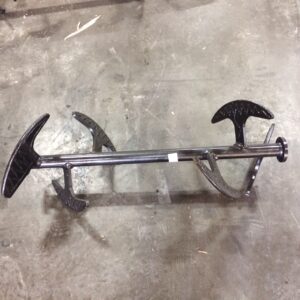
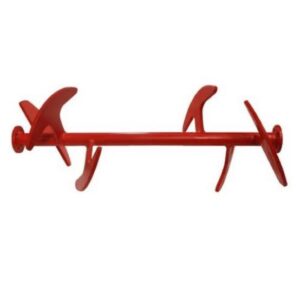
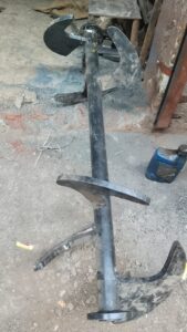
An agitator shaft in a concrete pump is the main rotating shaft that drives the hopper agitator to keep concrete uniformly mixed and flowing toward the pumping cylinders, preventing segregation and blockages in the hopper.
Basic role in the pump
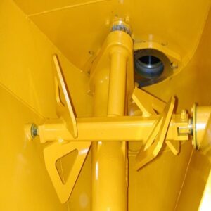
- The agitator shaft sits in the hopper and carries blades or paddles that rotate through the fresh concrete.
- Its rotation keeps coarse aggregate suspended, avoids settlement, and continuously feeds concrete into the S‑valve or rock valve inlet so the cylinders can pump smoothly.
Main functions
- Maintain homogeneity of concrete by gently remixing and breaking any tendency of coarse aggregates to separate from mortar in the hopper.
- Improve suction and filling of the pumping cylinders by pushing concrete toward the intake zone, reducing risk of cavitation and “voids” at the cylinder mouth.
- Help prevent clogging and bridging in the hopper, especially with harsh mixes or higher slump-loss, by providing continuous mechanical agitation.
Construction and drive
- The shaft is typically a heavy steel shaft supported in bearings on the hopper walls or via gear housing, with welded or bolted agitator arms and paddles along its length.
- It is driven either mechanically from the main PTO/gearbox or by a hydraulic motor, with torque transmitted through the shaft to the paddles to overcome the resistance of fresh concrete.
Design considerations
- Diameter, material, and surface treatment of the shaft are chosen for high torsional strength and wear resistance due to continuous operation in abrasive, cementitious slurry.
- Bearing arrangement and sealing at hopper walls are designed to exclude concrete slurry and wash water, protecting bearings from wear and corrosion.
- Agitator speed and blade geometry are selected so that mixing and feeding are effective but do not cause excessive aeration, segregation, or added vibration to the pump structure.
Agitator shafts are used in concrete pumps primarily to maintain mix uniformity and feed concrete reliably into the pumping system during construction operations.
Primary application in concrete pumps
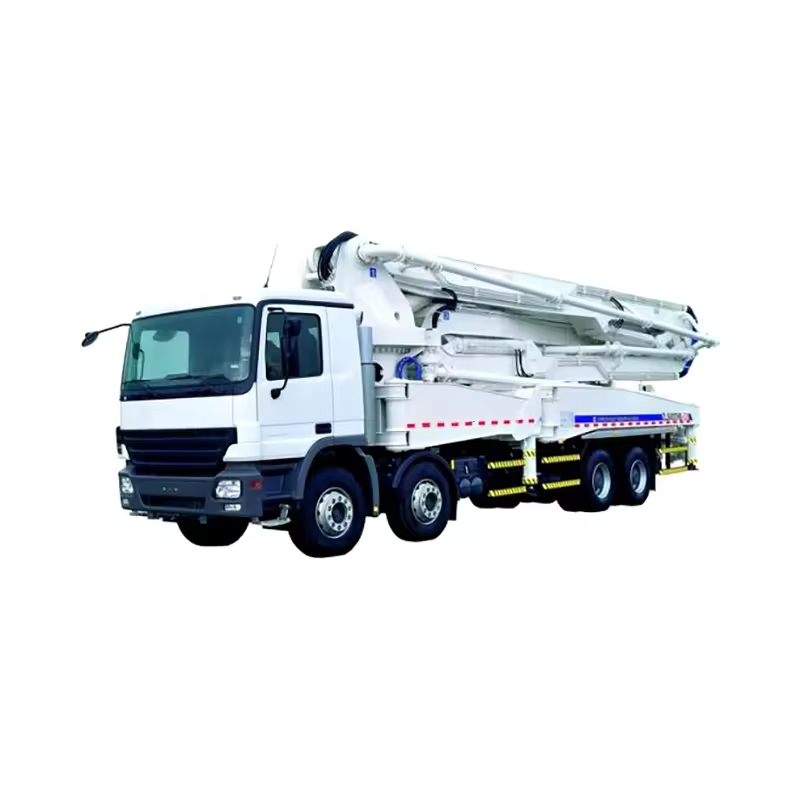
- Hopper agitation in truck‑mounted and stationary pumps: The shaft rotates arms/paddles in the hopper to keep aggregates suspended, prevent segregation, and push concrete toward the cylinder intake for continuous pumping.
- Ready‑mix delivery and placement: Essential in boom pumps and line pumps for high‑rise buildings, bridges, and large slabs where consistent flow is needed to avoid blockages and maintain output rate.
Applications by pump type
Pump Type | Agitator Shaft Role | Typical Use Cases |
Truck‑mounted boom pumps | Continuous hopper mixing during boom placement | High‑rise construction, tunnels, dams, industrial slabs |
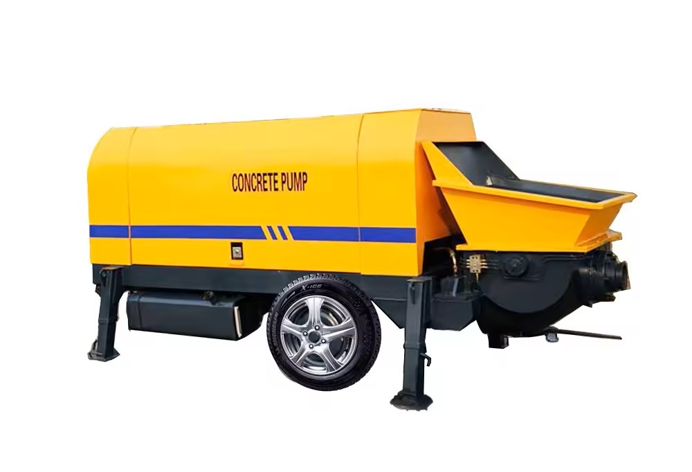
Line pumps (trailer/stationar | Hopper feeding for cylinder suction | Precast plants, roadworks, foundation pours |
Smaller pistol pumps | Basic anti‑settling in hopper | Small jobs, repairs, DIY pours |
Secondary and related applications
- Transit mixer unloading: Some mixer trucks have similar agitator shafts in the discharge chute or hopper to assist unloading into pumps or molds.
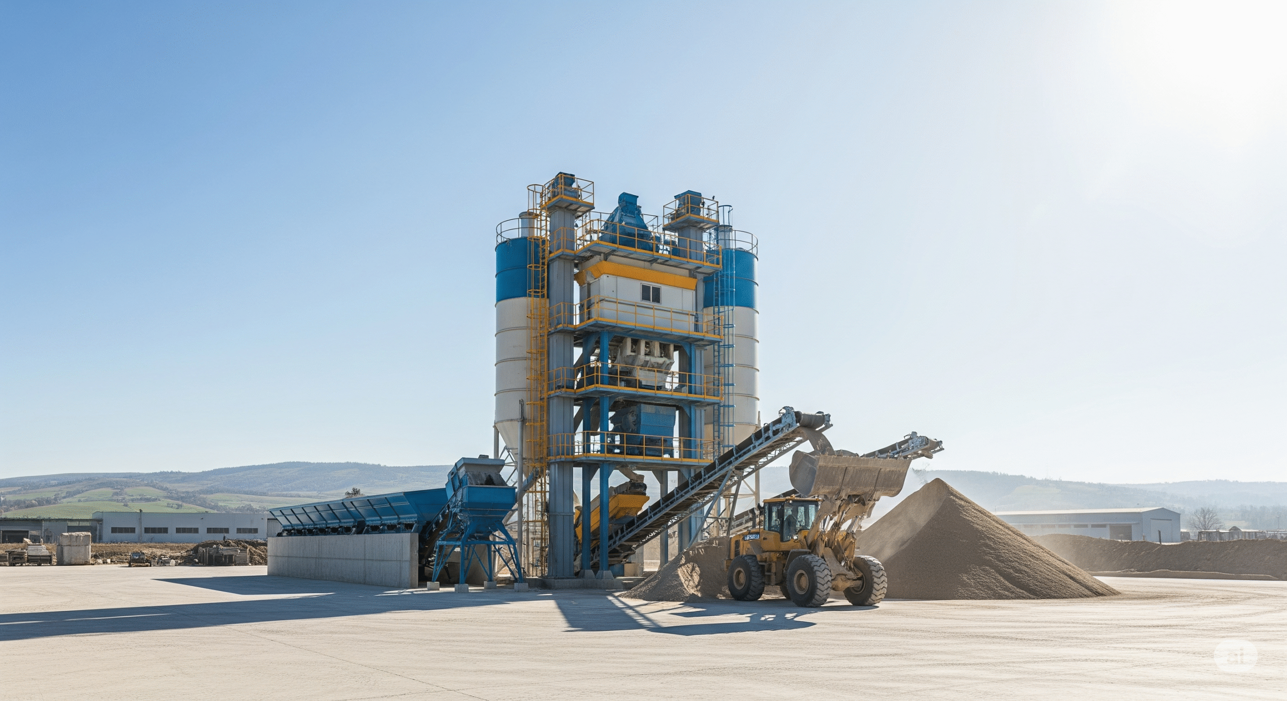
- Batch plant hoppers: Larger stationary batch plants use similar shaft agitators in surge hoppers to keep concrete moving before pump intake.
- Specialized pumps: Used in self‑loading concrete pumps or rotor‑type pumps where mixing and feeding are integrated into the pumping mechanism.
Key operational benefits in applications
- Reduces downtime from blockages by maintaining flow and homogeneity in the hopper.
- Improves pump efficiency and cylinder filling, especially with stiff or harsh mixes common in Indian site conditions.
- Extends life of downstream components by delivering uniform concrete without large lumps or voids.
The agitator shaft in a concrete pump operates in a high-abrasion, high-load, and wet alkaline environment. Because of this, the material of construction (MOC) is selected to provide strength, toughness, and excellent wear resistance.
Below is a clear explanation of the materials commonly used.
- Shaft Body Material
Alloy Steel (Most Common & Preferred)
Typical grades:
- 42CrMo4 / EN19
- AISI 4140 / 4145
- 40Cr
Why alloy steel is used:
- High tensile and yield strength
- Excellent fatigue resistance
- Good toughness under shock loads
- Can be heat treated for enhanced performance
Typical Properties (after heat treatment):
- Tensile strength: 900–1200 MPa
- Yield strength: 800–1000 MPa
- Hardness: 28–35 HRC (core)
This makes alloy steel ideal for resisting bending, torsion, and continuous torque from dense concrete mixes.
- Heat Treatment
Agitator shafts are normally:
- Quenched & tempered (Q&T)
- Sometimes induction hardened on high-wear zones
Benefits:
- Strong, tough core
- Improved fatigue life
- Resistance to sudden impact from aggregates
- Surface Protection & Wear Treatment
Concrete is highly abrasive, so additional protection is often applied:
Hardfacing / Wear Overlay
- Applied on shaft surface near blades
- Uses chromium or carbide-based electrodes
Coatings (Optional)
- Anti-corrosion or abrasion-resistant coatings
- Helps in alkaline and wet operating conditions
- Agitator Blades / Paddles Material
Although not part of the shaft body, blades directly affect shaft life:
Typical materials:
- Wear-resistant steel plates (HARDOX 400 / 450 / AR400)
- High-chrome cast steel (in some designs)
Blade features:
- Welded or bolted to the shaft
- Replaceable in heavy-duty designs
- High hardness: 400–500 HB
- Shaft Ends & Coupling Area
- Machined from the same alloy steel bar
- Keyway or spline areas often:
- Induction hardened
- Precision ground for perfect fit
This ensures reliable power transmission from gearbox or hydraulic motor.
- Bearings, Bushes & Seals (Associated Materials)
While not part of the shaft itself, they support it:
- Bearings: Hardened alloy steel (52100 bearing steel)
- Bushes: Bronze or hardened steel
- Seals: NBR / PU / Viton (for wet concrete environment)
Component | Material Used | Purpose |
Shaft body | Alloy steel (EN19 / 42CrMo / AISI 4140) | Strength & fatigue resistance |
Heat treatment | Quenched & tempered | Tough core, long life |
Wear surface | Hardfacing / induction hardening | Abrasion resistance |
Blades | HARDOX / AR steel | High wear resistance |
Shaft ends | Hardened alloy steel | Power transmission |
Step-by-Step Working Principle
- Concrete Enters the Hopper
- Fresh concrete is discharged from a transit mixer into the pump hopper.
- Due to its weight, aggregates tend to settle quickly if not disturbed.
- Agitator Shaft Starts Rotating
- The agitator shaft is driven by a hydraulic motor or gearbox connected to the pump system.
- It rotates at low speed but high torque, suitable for thick and heavy concrete mixes.
- Mixing & Stirring Action
- Helical or angled blades mounted on the shaft continuously stir the concrete.
- This action:
- Prevents segregation of aggregates and cement paste
- Breaks down lumps
- Maintains concrete workability and slump
- Guiding Concrete Toward the Suction Area
- The blade orientation is designed to push concrete toward the suction mouth of the pumping cylinders.
- This ensures a constant and uniform feed to the pump pistons or S-valve.
- Continuous Re-circulation
- As pumping continues, concrete is constantly:
- Drawn into the cylinders
- Replaced by fresh material from the hopper
- The agitator shaft keeps this cycle smooth and uninterrupted.
Typical features
The agitator shaft in a concrete pump is designed for heavy torsional load, abrasion, and reliable feeding of concrete from the hopper to the pumping cylinders, so its main features focus on strength, wear resistance, and smooth operation.
Structural and material features
- High-strength steel construction: Typically a solid medium/high-strength carbon or alloy steel shaft to withstand torsion, bending, and fatigue from continuous mixing of stiff concrete.
- Machined journals, shoulders, and ends for accurate fit of bearings, seals, and couplings, ensuring alignment and reducing stress concentrations.
- Weldable sections or bosses along the shaft to attach agitator arms/paddles that push concrete toward the intake.
Wear and corrosion resistance
- Local surface hardening (induction/case hardening) on bearing and seal seats to improve wear life in an abrasive and wet environment.
- Design to minimize slurry contact on critical seating areas, often with proper seal lands and protective sleeves near the hopper wall penetrations.
- Compatible with anti-corrosion coatings or protective paints on non-working surfaces to reduce rust during idle periods and washing cycles.
Functional and performance features
- Geometry and stiffness selected so that the shaft can transmit sufficient torque for agitation without excessive deflection or vibration, contributing to stable hopper operation.
- Mounting positions for arms/paddles arranged to promote continuous flow toward the suction opening, prevent bridging, and keep aggregates in suspension in the hopper.
- Designed for reversible rotation in many pumps, allowing “reverse” function to help clear minor jams or redistribute concrete in the hopper.
Mounting, sealing, and maintenance features
- Supported in robust bearings outside the hopper with grease‑lubricated housings and seals to keep out concrete and wash water.
- Shaft ends prepared with keyway/spline/thread features to connect quickly to a hydraulic motor or gearbox, simplifying assembly and replacement.
- Straightness and concentricity controlled in manufacturing to reduce bearing load, noise, and wear, improving service life and reliability.
Safety and operational features
- Designed to work with guards and hopper grids so contact with the rotating shaft and paddles is minimized for operator safety.
- Agitator speed (through shaft drive design) matched with pump capacity to avoid over‑agitation, unnecessary energy consumption, and extra boom vibration during pumping.
Specifications
Specifications can vary by manufacturer, pump capacity, and application, but the following are the standard engineering characteristics used in the concrete pump industry:
- Material
- High-strength alloy steel (e.g., 42CrMo, 40Cr, AISI 4140)
Good toughness, fatigue resistance, and wear resistance
- Often heat-treated (quenched & tempered) for durability
- Surface may be hardfaced or induction-hardened on wear zones
Typical Mechanical Properties
- Yield strength: ≥ 800–1000 MPa
- Tensile strength: ≥ 950–1200 MPa
- Dimensions & Geometry
These vary with pump model, but common values include:
Feature Typical Range
Shaft diameter Ø 40–80 mm
Overall length 500–1200 mm (depends on pump/hopper size)
Spline / Keyed section Sized to match coupling/drive system
Number of mixing blades 2–4 blades/paddles
Blade angle 30°–60° helical angle for optimal mixing
The shaft is usually a solid round bar with welded or bolted mixing paddles.
- Mixing Blades / Paddles
- Shape: Helical or angle-cut blades
- Material: Abrasion-resistant steel (e.g., HARDOX, AR400)
- Attachment: Welded or bolted to the shaft
- Pitch & angle: Engineered to maximize concrete turnover and prevent lumping
- Drive & Coupling Interface
The agitator shaft rotates via a:
- Gearbox or direct drive motor
- Keyed shaft end or splined coupling
- Typically sealed bearings and guards