Hydraulic cylinders are everywhere around us, we see them in our daily life all the time without maybe even realizing if we don’t specifically pay attention: in excavators, trucks, forklifts, tractors, aerial platforms, mining equipment – you name it. Hydraulic cylinder is one of the four main components of a hydraulic system, whereas hydraulic system is a technology where fluid, most commonly hydraulic oil, is used to move energy from a motor to an actuator: most commonly, a hydraulic cylinder.
A hydraulic cylinder (also called a linear hydraulic motor) is a mechanical actuator that is used to give a unidirectional force through a unidirectional stroke. It has many applications, notably in construction equipment (engineering vehicles), manufacturing machinery, elevators, and civil engineering. A hydraulic cylinder is a hydraulic actuator that provides linear motion when hydraulic energy is converted into mechanical movement. It can be likened to a muscle in that, when the hydraulic system of a machine is activated, the cylinder is responsible for providing the motion
Hydraulic cylinder is a part of a machine’s hydraulic system. Simply said, hydraulic cylinder is a hydraulic actuator which creates linear movement by converting the hydraulic energy back to a mechanical movement. Hydraulic cylinder can be compared to a muscle; with the machine’s hydraulic system, it creates the movement – therefore it is like a muscle.
In the hydraulic transmission, the medium is liquid, usually oil, of which we are also talking about this text. The basic concept of hydraulics is that when the power machine rotates the pump, a volume flow is formed (the volume of liquid passing through the cross-section per unit of time, which’s unit in the SI is m3/s). The pressure of the hydraulic system is determined by the load which is caused either with the cylinder or valve which then resists the flow of the liquid flow caused by the hydraulic pump.
The pressure spreads evenly to every direction in the system and effects to all hydraulic system’s closed spaces’ surfaces evenly; this effect is called Pascal’s law.
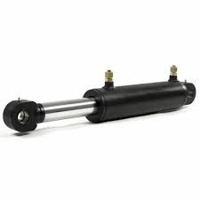
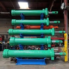
A hydraulic cylinder is a tube that produces linear actuation utilizing hydraulic pressure. Basically, the pressure of a hydraulic fluid forces a piston to move in either a pushing or pulling motion.
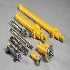
Hydraulic cylinders are the moving force in many commercial as well as industrial manufacturing concerns. Some of their applications are as detailed below:
- Aerospace: Landing gears and wing flaps
- Automotive: Earth Moving Equipment
- Agriculture: Tractors
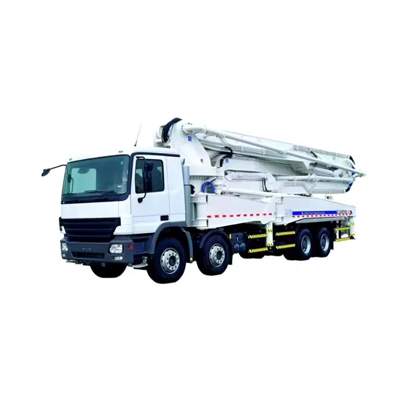
- Civil works: Excavators, Bulldozers, and attachments
- Oil and gas industries
- Power Generation: Flow controls for the water gates
- Motorway repairs and maintenance
- Mining: Excavators
Functionally, a hydraulic cylinder operates by converting hydraulic energy into linear mechanical motion to perform work. When pressurized hydraulic fluid is directed into one side of the cylinder, it pushes the piston, causing the piston rod to extend or retract. This linear motion can be used to lift, push, pull, or position loads with great force and precise control.
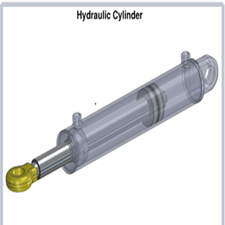
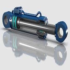
The main functional components include the cylinder barrel, piston, piston rod, and hydraulic fluid ports. Pressurized fluid enters through the ports to move the piston within the barrel. The movement is controlled by valves that regulate the flow and pressure of the hydraulic fluid, allowing for smooth and adjustable speed and force. The system’s pressure enables the cylinder to exert force on the load, often multiplying the input force many times over.
Hydraulic cylinders are used in controlling machinery movements such as boom lifting in excavators, opening and closing mechanisms in heavy equipment, and precise positioning of components. They enable repetitive, controlled linear motion in environments requiring high power density, load-holding capability, and reliability. This functional operation makes them essential actuators in construction, manufacturing, automotive, and agricultural machinery
A hydraulic cylinder works by using pressurized hydraulic fluid to create linear motion and force. When the hydraulic pump pushes fluid into one side of the cylinder through the inlet port, the fluid pressure forces the piston to move, extending or retracting the piston rod attached to the piston. This movement transfers mechanical power to perform tasks like lifting, pushing, or pulling.
The piston inside the cylinder divides the cylinder into two chambers. By controlling the flow of fluid into and out of these chambers via valves, the direction and speed of the piston rod's movement are regulated. Pressurized fluid entering one chamber creates pressure differential that moves the piston, and fluid from the opposite chamber is pushed out through the return port.
Seals inside the cylinder maintain the pressure by preventing fluid leakage and ensure smooth operation. The hydraulic fluid acts as the medium transmitting force, enabling the cylinder to exert greater force than manual operation would allow. This makes hydraulic cylinders highly efficient for heavy-duty linear actuation in various machines and equipment
Key features of hydraulic cylinders include high power density, robust sealing systems, and precise controllability for reliable linear actuation.
Structural Features
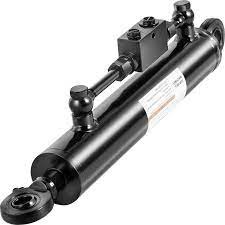
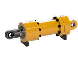
Cylinder Barrel and Piston: Durable housing with a precisely fitted piston to contain pressurized fluid and generate force.
Piston Rod: Strong, polished rod attached to the piston for transmitting linear motion, often with overload protection.
Seals and Cushioning: Low-leakage seals to prevent fluid loss and cushioning mechanisms (e.g., plunger or conical structures) for smooth deceleration and reduced shock.
Performance Features
High Pressure Capacity: Operates at pressures up to 70 MPa or more, enabling force output like 70 kN in compact designs.
Load-Holding and Energy Efficiency: Passive load-holding via hydraulic locks, energy recovery, and low-leakage valves for sustained positioning without continuous power.
Control Integration: Built-in sensors for pressure, position, load, and temperature, plus servo valves for high-bandwidth force/impedance control.
Durability and Design Features
Buckling Resistance: Optimized materials and geometry to withstand compressive loads and buckling.
Compactness and Scalability: Additive manufacturing for integration and scalability up to 80 kW, suitable for robotics and heavy machinery.
Core Sizing Specifications
Inside Diameter (ID) / Bore: Selected per ISI standards, preferred numbers, seamless pipe availability, or seal sizes; determines force capacity via piston area.
Stroke Length: Total travel distance of piston rod; influences stopper tube use for long strokes to prevent buckling.
Piston Rod Diameter: Sized for buckling resistance and sealing; often called RAM when nearly equal to bore; supports threading, hollow, or dual-end designs.
Pressure and Performance Specs
Working Pressure: Chosen below system max with safety factor; basis for tube thickness (thin/thick cylinder) and end-plug design to limit stresses.
Capacity / Force Output: Calculated from pressure × effective area (full bore vs. annular/rod side); critical for press applications.
Mounting Type: Front/rear tube flange, tie-rod, threaded, bolted, or custom; dictates flange size, bolt circle, and enclosure integration.
Speed and Flow Rate: Cylinder speed depends on oil flow rate and bore size; port diameters are selected accordingly to optimize speed and minimize pressure loss.
Sealing Materials: Different packing materials like nitrile, urethane, and fluorine rubber rated for temperature and abrasion resistance.
Buckling Considerations: Buckling charts aid in selecting piston rod diameter and max stroke capacity for varying mounting conditions.
Cushioning Features: Cushions (rod/head/both ends) reduce impact at stroke ends to ensure smooth operation.
Additional Functional Specs
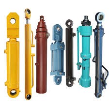
Construction Type: Single/double action, differential, telescopic, non-rotating, or compound (e.g., intensifier for high pressure >1500 bar).
For Examples:
- Double-acting cylinders enriched with cushioning and various seals for leak-proof operation.
- Telescopic cylinders for long stroke in compact axial lengths.
- Rotary cylinders for linear-to-rotary conversion with torque data.
- Compact cylinders with aluminum or steel tubes for space-efficient uses.
- Application-specific cylinders like mill type for heavy industries.
Ports and Features: Oil port size (flow-based), bleed-off ports for air removal, cushioning type (fixed/variable) for speed control.