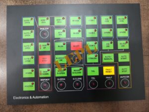
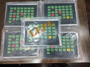
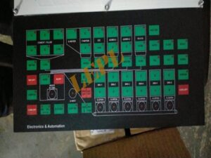
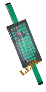
A PCB-based membrane keypad is a rugged human–machine interface (HMI) commonly used in concrete batching plants to operate and control the batching process.
Introduction
In a concrete batching plant, reliability and accuracy are critical because operators must control material weighing, mixing cycles, and discharge sequences in harsh environments. A PCB (Printed Circuit Board) base membrane keypad combines a flexible membrane overlay with a rigid PCB circuit, providing a durable, precise, and easy-to-use control interface for plant operators.
The PCB base contains copper tracks and electronic components that ensure stable electrical performance.
The membrane layer (usually polyester or polycarbonate) sits on top, with printed keys, symbols, and legends.
When a key is pressed, it completes a circuit on the PCB, sending a command to the batching plant control system or PLC.
Why it is used in concrete batching plants
High durability: Resistant to dust, cement powder, moisture, vibration, and temperature variations.
Accurate operation: PCB circuits provide consistent key response, important for precise batching and timing.
Sealed design: The membrane surface is easy to clean and protects electronics from harsh site conditions.
Compact and reliable: Takes less space than mechanical switches and has a long service life.
Customizable: Key layouts, symbols, and functions can be designed according to plant requirements.
A PCB-based membrane keypad is an essential control component in concrete batching plants, offering a balance of robustness, precision, and ease of operation. Its ability to withstand harsh industrial environments while delivering reliable performance makes it a preferred choice for modern batching plant control panels.
Applications of PCB-Based Membrane Keypads in Concrete Batching Plants
PCB-based membrane keypads are widely used as operator input interfaces in concrete batching plants. Their applications cover both process control and plant operation management, especially in dusty and harsh industrial environments.
- Batch Process Control
The keypad allows operators to directly control the concrete production cycle, including:
- Starting and stopping batching operations
- Initiating mixing cycles
- Controlling discharge of concrete into transit mixers or hoppers
This ensures accurate and repeatable batching sequences.
- Material Selection and Dosing
Operators use the keypad to:
- Select raw materials such as cement, sand, aggregates, water, and admixtures
- Adjust material quantities for different concrete mix designs
- Switch between stored mix recipes
The PCB-based keypad provides precise input for correct dosing and mix consistency.
- Manual and Automatic Mode Operation
Keypads enable:
- Switching between manual mode (for maintenance or testing)
- Automatic mode (for normal production runs)
This flexibility is essential for plant commissioning, troubleshooting, and routine operation.
- Parameter Setting and Calibration
PCB membrane keypads are used to:
- Enter calibration values for load cells and weighing systems
- Set timing parameters for feeders, conveyors, and mixers
- Adjust water and admixture flow rates
Accurate keypad input ensures reliable weighing and batching performance.
- Alarm Handling and System Reset
In batching plants, alarms are common due to:
- Overweight or underweight conditions
- Conveyor or mixer faults
- Sensor or communication errors
The keypad is used to:
- Acknowledge alarms
- Reset faults
- Restart operations after resolving issues
- Equipment Control
Keypads provide direct control for:
- Conveyors and belt feeders
- Screw conveyors for cement
- Bucket elevators and skip hoists
- Vibrators and gates
This allows operators to manage plant equipment safely and efficiently.
- Recipe Management
Operators can use the keypad to:
- Create, edit, and store concrete mix recipes
- Select different grades of concrete quickly
- Modify proportions based on project requirements
This improves productivity and reduces human error.
- Maintenance and Service Functions
During maintenance, the keypad is used for:
- Jogging motors and feeders
- Testing individual components
- Running diagnostic routines
The rugged membrane surface withstands frequent use during service activities.
- Harsh Environment Operation
Because concrete batching plants operate in dusty, wet, and vibrating conditions, PCB-based membrane keypads are ideal for:
- Outdoor and semi-outdoor control panels
- Operator cabins exposed to cement dust
- Control desks requiring easy cleaning
PCB-based membrane keypads play a critical role in controlling, monitoring, and managing concrete batching plant operations. Their applications range from batch control and material dosing to alarm handling, recipe management, and maintenance, making them an indispensable interface in modern concrete production systems.
A PCB based membrane keypad for a concrete batching plant is a multi layer assembly built on a rigid glass epoxy PCB (FR 4) with a printed plastic overlay on top and adhesive/spacer layers in between. Each material is chosen to survive cement dust, vibration, and outdoor/plant conditions while still giving clear graphics and reliable key operation.
Rigid PCB base and conductors
- The structural backbone is a glass epoxy PCB (typically FR 4) that carries the copper tracks, key pads, and any mounted components such as LEDs, resistors, and connectors.
- Copper foil on the PCB forms the row/column matrix pads for each key, with standard PCB solder mask and legend inks used on non contact areas.
Graphic overlay (front face)
- The top visible layer is usually polycarbonate or polyester film, reverse printed with legends, symbols, and color coding for batching functions (Start, Stop, Auto/Manual, Recipe, digits, etc.).
- For harsh industrial use, special grades of polyester are often preferred because they give better scratch, chemical, and UV resistance than standard polycarbonate while still allowing embossing for tactile feel.
Spacer, dome and adhesive layers
- Spacer layers are polyester films with cut outs under each key; they keep the PCB pads normally open and allow air to move when the dome is pressed and released.
- Tactile feedback is provided by stainless steel or gold plated metal domes, or embossed polyester “snap” domes, placed between overlay and PCB pads to short the contacts when pressed.
- Double sided acrylic adhesive films (often 3M type membrane switch adhesives) bond overlay–spacer–PCB together and may also provide a rear adhesive for mounting the keypad to the batching plant panel.
Additional mechanical and protective elements
- Heavy industrial grade materials and protective films are used on the overlay surface to resist abrasion, cement fines, moisture, and cleaning chemicals in batching cabins.
- Some designs use clinching studs or metal back plates, or thicker PCBs, to stiffen the assembly and facilitate screw mounting on the front panel or door of the batching plant control cabinet.
Typical material combinations in batching plant keypads
- Product descriptions for CP30 PCB type batching plant keypads mention glass epoxy PCB plus a polycarbonate or PVC/PET graphic layer, with “heavy industrial grade materials” and high quality adhesive to withstand daily wear and tear.
- Many PCB based membrane keypads for industrial automation are specified as “polycarbonate or PET overlay + polyester spacer + silver printed polyester or copper circuit PCB + acrylic adhesive,” optimized for long life and IP rated sealing.
The working principle of a PCB‑based membrane keypad in a batching plant is that each key is a momentary switch which, when pressed, electrically connects two PCB tracks (row and column); the batching controller continuously scans these tracks and interprets any new connection as a keypress command. All batching functions (start, stop, jog, recipe entry, etc.) are triggered in software based on which row–column pair is detected as closed.
- Layer structure and contact formation
- The keypad has a graphic overlay on top and a rigid FR‑4 PCB beneath; the PCB carries interdigitated copper pads for each key and routing tracks for rows and columns.
- Between overlay and PCB there is a spacer/dome layer; when the operator presses a key area, a metal/poly dome or conductive element collapses and bridges the PCB pads, closing the contact.
- Electrical behavior of each key
- In normal (unpressed) state, all key contacts are open; the corresponding row and column lines are electrically isolated.
- On pressing, the dome brings the two pads together so that the row line and column line become electrically connected, forming a low‑resistance path that the controller input senses as a logic change.
- Matrix scanning by the controller
- The keypad is wired as a matrix: several row lines and several column lines go from the PCB to the batching controller keyboard connector.
- The controller periodically drives one set of lines (e.g., rows) with a logic signal and reads the other set (columns); if a row and a column show continuity during a scan, the firmware decodes that row–column combination as a specific key.
- Debouncing and key decoding in firmware
- Mechanical and dome contacts bounce for a few milliseconds; the controller applies debounce logic (e.g., waiting for a stable signal for a set time) before confirming a valid key press.
- The firmware also handles long‑press/auto‑repeat if required (for increment/decrement keys) and then maps the decoded key to plant functions like batch start, manual gate open, recipe select, numeric entry, etc.
5. Integration with PCB‑based design
- Because the switch matrix is on a rigid PCB, components such as pull‑up resistors, indicator LEDs, and connectors can be mounted directly on the same board, simplifying wiring and improving reliability under vibration.
- The PCB keypad assembly plugs into the batching plant controller or panel harness as a single unit; from the controller’s perspective, it behaves as a standard scanned key matrix, independent of the harsh external environment thanks to the sealed overlay.
Below is the Step by Step Process for more better understanding
Below is a clear, step-by-step explanation of the working principle of a PCB-based membrane keypad as used in concrete batching plants, written in an engineering/industrial documentation style.
- Basic Concept
A PCB-based membrane keypad works on the principle of a momentary electrical contact.
When an operator presses a key on the membrane surface, it temporarily closes an electrical circuit on the PCB, sending a signal to the batching plant controller (PLC or microcontroller).
Once the key is released, the circuit opens again, and the signal stops.
- Main Functional Layers Involved
The keypad typically consists of the following layers (from top to bottom):
- Graphic Overlay
- Membrane Switch Layer (with conductive pads or domes)
- Spacer Layer
- Printed Circuit Board (PCB)
Each layer plays a specific role in the working principle.
- Step-by-Step Working Principle
Step 1: Idle (No Key Press)
- In the normal state, the membrane switch contacts are separated from the PCB tracks.
- The spacer layer maintains a small air gap between the conductive membrane and PCB contacts.
- No electrical signal is sent to the controller.
Step 2: Key Press by Operator
When an operator presses a key (e.g., START BATCH, WATER ADD, MIXER ON):
- The pressure deforms the membrane.
- The conductive pad or metal dome under that key moves downward.
- It bridges the corresponding PCB contact pads.
Step 3: Circuit Closure
- Once the membrane contact touches the PCB pads:
- An electrical circuit is completed.
- A voltage change is detected at the keypad output lines.
- This change represents a specific key command.
Example:
Key pressed → Row 2 and Column 3 connected → Controller identifies “START MIXER”.
Step 4: Signal Processing by Controller
- The PCB routes the signal through:
- Matrix circuits (rows and columns), or
- Direct individual key lines
- The signal is sent via:
- Flat flexible cable (FFC/FPC) or ribbon cable
- The PLC or control unit scans the keypad and interprets the input.
Step 5: Execution of Batching Function
- Based on the detected key:
- PLC executes the programmed action:
- Start conveyor
- Open aggregate gate
- Start mixer
- Add water or admixture
- Stop batch cycle
Step 6: Key Release
- When the operator releases the key:
- The membrane returns to its original position.
- The circuit opens again.
- The signal stops.
- The system is ready for the next input.
For concrete batching plants, the key features of both flexible and PCB based membrane keypads revolve around durability in harsh conditions, reliable input for process control, and easy integration with the controller/HMI.
Environmental and mechanical robustness
- Sealed front surface (no open moving parts) gives strong resistance to dust, cement splashes, moisture, and cleaning liquids, which is critical in batching cabins and near aggregates.
- Industrial grade construction with wear resistant films and heavy duty materials allows the keypad to withstand daily operation, vibration, and temperature variations on construction sites.
Operator interface and usability
- Low profile, feather touch keys provide quick, light force operation for frequent use, reducing operator fatigue during manual and semi automatic batching.
- Custom graphic overlay with clear legends (Start, Stop, Auto/Manual, Recipe, numeric keys, fault/acknowledge, etc.) offers intuitive, user friendly operation and minimizes operator error.
Electrical and functional characteristics
- Multi layer membrane structure ensures stable contact resistance and long key life, supporting thousands to millions of actuations without loss of function.
- PCB based versions allow direct routing on FR 4, robust connectors, and integration of LEDs and simple components, improving signal integrity and reliability in CP series and similar batching controllers.
Maintenance and installation benefits
- Flat, non porous surface is easy to clean and does not trap fines, so routine wiping is enough to maintain readability and hygiene on the panel.
- Designed as plug and play replacement parts for specific plant models (e.g., CP30 PCB type keypad), with precise cutting, matching pin out, and strong adhesive or mounting, simplifying service and retrofit work.
Cost and system level advantages
- Thin, compact construction gives a neat panel layout and saves space compared to discrete push buttons and indicator lamps.
- Provides a low cost alternative to full touchscreen HMIs while still enabling reliable process input, parameter setting, and fault acknowledgement in concrete batching automation.
Below are the Important Specifications
- Physical & Mechanical Specifications
Construction
Layers: Graphic overlay + membrane switch layers + spacer + PCB
Thickness: ~0.4–1.5 mm (overall panel depends on overlay & domes)
Key Type: Polyester/Polycarbonate overlay with tactile domes or metal domes
Dimensions
Custom panel size: e.g., 100 × 200 mm (varies per control panel)
Actuator area per key: ~8–15 mm² (custom)
Tactile Feedback
Contact Force: 150–400 g/cm² (depends on dome type)
Travel/Feel: 0.2–0.5 mm tactile travel
Mounting
Method: Adhesive backing / threaded standoffs / snap-fit into panel cut-out
- Electrical Specifications
Contact Characteristics
Contact Type: Carbon/Gold printed circuit contacts
Contact Resistance: ≤ 500 Ω initial (depends on material)
Insulation Resistance: ≥ 100 MΩ @500V DC (good for noise immunity)
Electrical Ratings
Operating Voltage: Typically 5–24 V DC (PLC/microcontroller compatible)
Switch Current Rating: ~10–50 mA (logic-level, not load switching)
Bounce Time: ≤ 10 ms typical
Interface
Output Type: Matrix (e.g., 4×4, 5×5) or direct mapped lines
Connector: FFC/FPC cable or solder pads
Cable: Flat flexible cable or ribbon cable with locking
- Environmental & Durability Specifications
Ingress Protection
IP Rating: IP65 or higher (sealed against dust and splashes)
Operating Temperature
Range: −20°C to +70°C (typical industrial)
Storage Temperature
Range: −40°C to +85°C
Humidity
Operating: 10%–95% RH (non-condensing)
Vibration & Shock
Vibration: Complies with industrial standards (e.g., IEC 60068)
Shock: Resistant to moderate mechanical shock
Lifespan / Endurance
Switch Life: > 1,000,000 cycles (some designs > 5 million)
- Overlay & Material Specifications
Graphic Overlay
Material: Polyester (PET) or Polycarbonate (PC)
Thickness: 0.1–0.3 mm
Surface Finish: Matte or glossy UV printed
Legends: Screen printed, UV cured (resistant to abrasion)
Dome / Tactile Elements
Type: Metal domes (longer life) or formed polyester domes
Actuation Force: Adjustable via dome choice
Adhesives
Type: High-bond acrylic adhesive (for secure panel mounting)
Temperature Stability: −40°C to +100°C
Backlighting (if fitted)
LED color: Red / Green / Blue / White / Bi-color
Brightness: > 1000 mcd typical
Control: Direct drive or via controller
Example Specification Summary (Typical)
Parameter Typical Value
Operating Voltage 5–24 V DC
Contact Life >1,000,000 operations
Operating Temp −20°C to +70°C
IP Rating IP65 (dust & splash resistant)
Tactile Travel 0.2–0.5 mm
Key Actuation Force 150–400 g/cm²
Connector FFC/FPC or solder pads
Overlay Material PET/PC UV printed
Backlight Optional LEDs