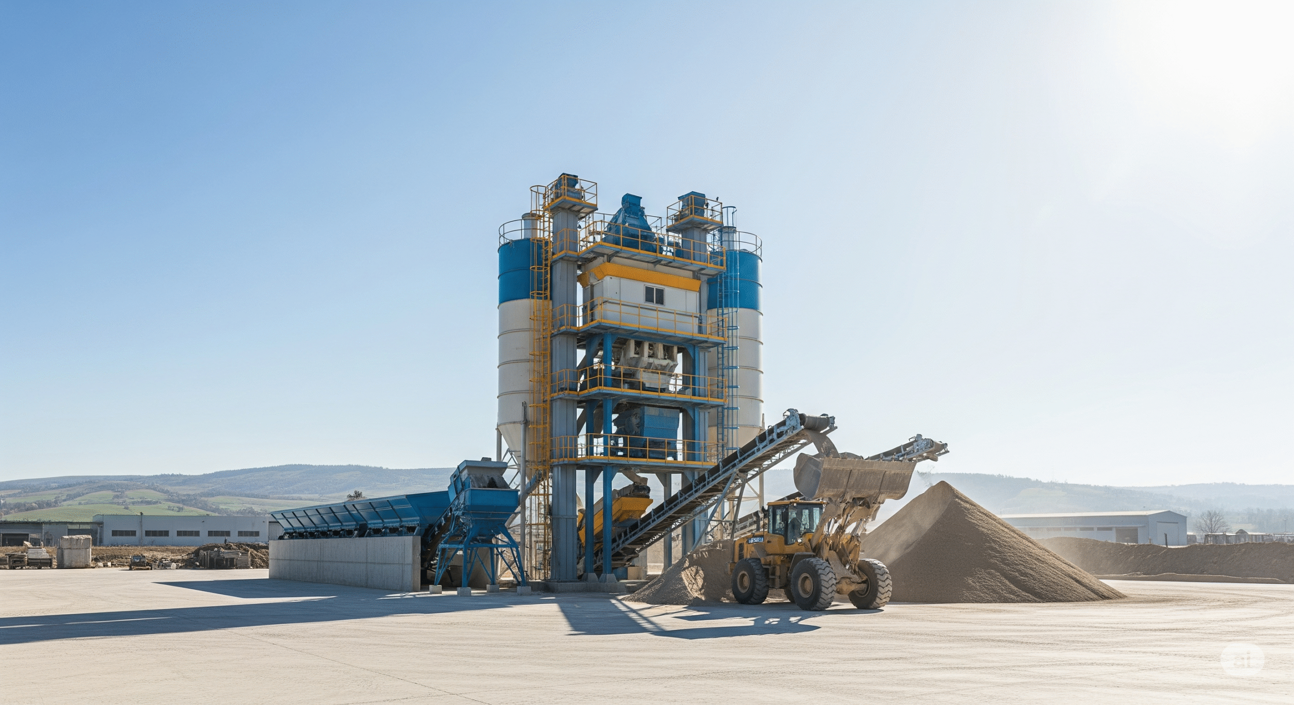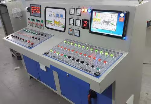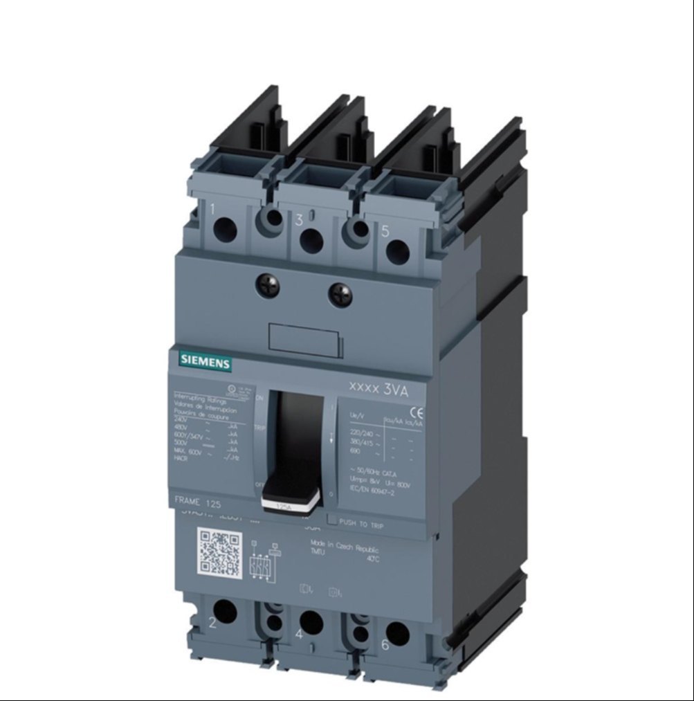
Concrete batching plants use several dust-control and process filters to prevent cement dust emission, protect equipment, and maintain environmental compliance. These filters are installed in cement silos, conveyors, mixers, batching towers, and pneumatic conveying lines.
Concrete batching plants use several distinct filter types: mainly dust filters on silos and transfer points, and water/solid separation filters on the reclaim system and slurry line.
Cement Silo Top Filter (Silo Vent Filter)
These are mounted on cement / fly ash silos to vent air during pneumatic filling while trapping dust.
Cylindrical or rectangular housing, bolted to a flange on silo roof, with clean air outlet up.
Filter elements:
- Pleated cartridge elements (modern plants), or
- Fabric bag elements with cages (older / high‑temp).
- Cleaning: pulse‑jet compressed air (most common) or mechanical shaker.
Purpose
- Mounted on top of cement silos to remove dust during pneumatic cement filling.
- When cement is blown into the silo from tanker trucks, displaced air carrying cement dust exits through the filter.
- The filter traps dust and allows clean air to escape.
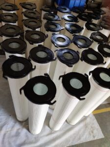
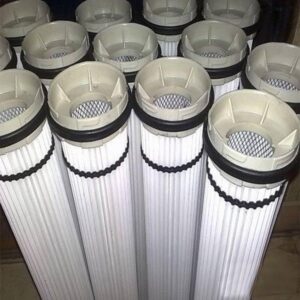
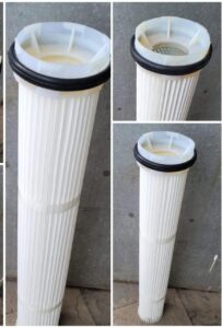
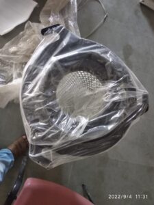
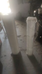
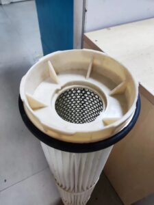
- Dust-laden air rises in the silo.
- Air passes through cartridge filter elements.
- Dust stays on the filter surface.
- Pulse-jet compressed air cleans cartridges.
- Dust falls back into the silo.
Ranges as per Manufacturers.
- Airflow: about 150–1500 m³/h per silo filter (small to large silos).
- Filter area: ~10–60 m² per unit (cartridge systems give more area in same footprint).
- Cartridge size examples:
- OD: 120–160 mm.
- Length: 600–1200 mm.
- Pleated media, surface area per cartridge: ~5–15 m² depending on pleat geometry.
- Bag type elements:
- Diameter: typically 125–160 mm.
- Length: 2–3 m.
- Number of bags: 6–24 bags for silo‑top units.
- Housing: carbon steel, often epoxy/polyurethane coated; sometimes stainless steel 304/316 for high corrosion environments.
- Filter media:
- 100% spun‑bond polyester, surface treated (e.g., PTFE membrane, antistatic, oil‑water repellent) for cement.
- Alternative fabrics: polyester felt, aramid for higher temperature, fiberglass fabric for special baghouses.
- Gaskets: closed‑cell neoprene / EPDM for dust‑tight sealing, NBR rubber
- Fasteners: galvanized or stainless steel.
- Air‑to‑cloth ratio: around 1–5 m³/min per m² cloth for fine cement dust (so fairly low A/C ratio for long life).
- Cleaning pressure: pulse air about 4–6 bar, with solenoid‑operated diaphragm valves.
- Emission limit: modern units designed to achieve <10 mg/Nm³ dust; some claim 99.99% efficiency.
Typical specifications
Parameter Typical Value
Filtration area 12–24 m²
Airflow capacity 800–1400 m³/h
Filtration efficiency up to 99.9%
Cleaning method Pulse-jet compressed air
Air pressure 5–7 bar
Operating temperature −20°C to +80°C
These filters often use polyester or PTFE membrane cartridges with steel housing.
Common sizes
Model Cartridges Filter Area
Small silo 4 cartridges 12 m²
Medium silo 7 cartridges 24 m²
Large silo 12–24 cartridges 200–500 m²
Industrial silo filters can reach filtration areas above 500 m² in large cement plants.
What you’d usually see on GA and fabrication drawings for a silo vent:
- General arrangement:
- Plan showing bolt circle, inlet (from silo headspace), clean air outlet, ladder/platform interface.
- Elevation showing overall height, cartridge/bag length, compressed air header, access door.
- Sectional view:
- Filter elements, tube sheet (plate where bags/cartridges mount), pulse pipes and nozzles, dust discharge path back to silo.
- Detail drawings:
- Tube sheet hole pitch and pattern.
- Cartridge/bag mounting (snap band, threaded rod, or bayonet‑type).
- Pulse valve manifold and air inlet.