Top-Mounted and Ground-Mounted Dust Collectors for Concrete Batching Plants
Both top-mounted and ground-mounted dust collectors are normally pulse-jet fabric-filter baghouses or cartridge collectors. The principal difference is installation location: a top-mounted/bin-vent unit sits directly on a cement or fly-ash silo, while a ground-mounted central collector serves several dust-generation points through ducting
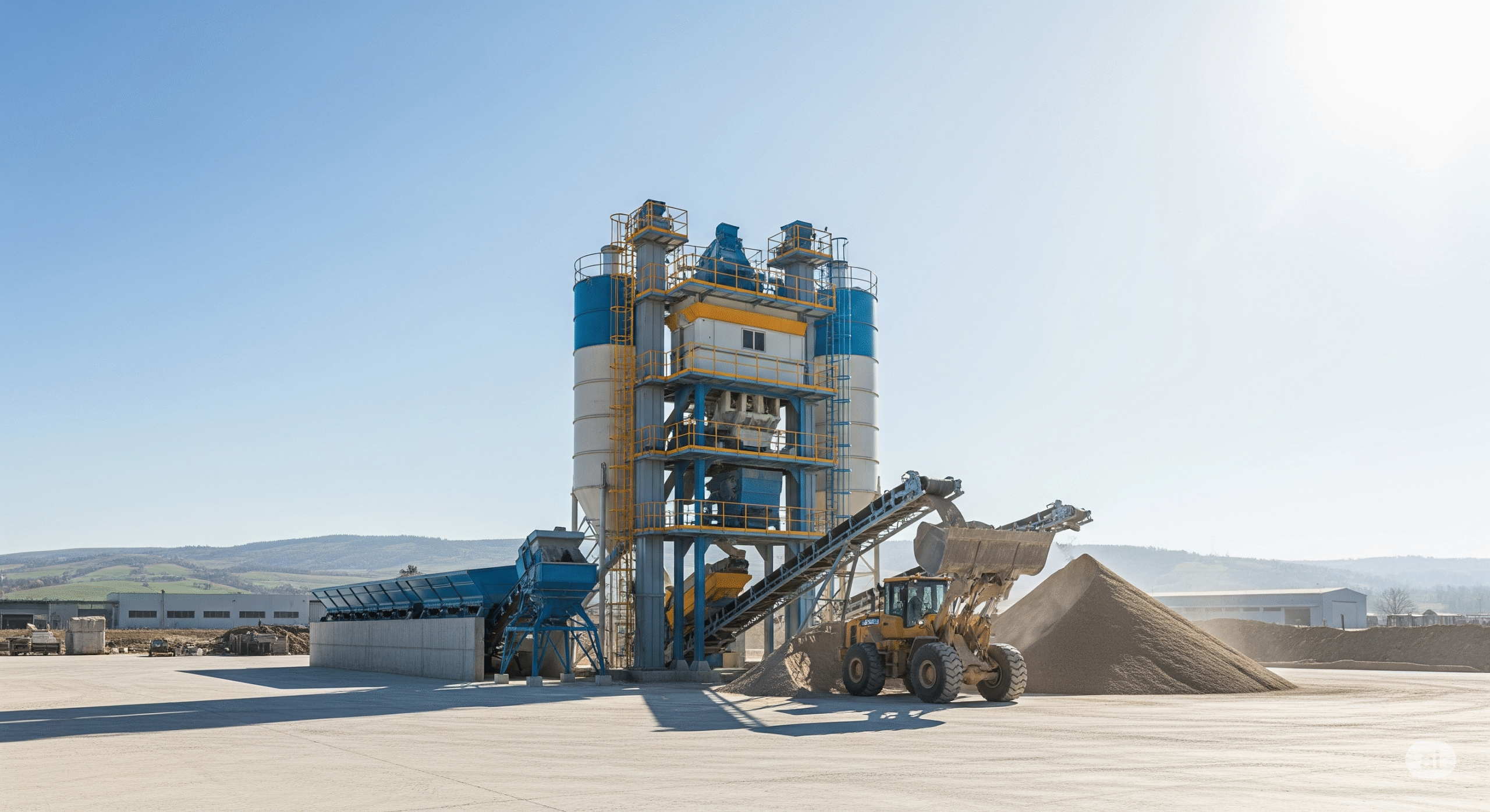
Concrete batching plants generate cement, fly ash, silica-rich aggregate fines, and admixture dust during silo filling, pneumatic conveying, aggregate weighing, mixer charging, and truck loading. Fabric-filter dust collectors are the standard control technology for silos, conveyors, weigh batchers, and truck-loading points.
Typical collection points are:
- Cement and fly-ash silo vents during bulker unloading.
- Cement weigh hopper / batcher vents.
- Screw-conveyor and pneumatic-conveyor transfer points.
- Mixer charging and truck-loading hoppers.
- Aggregate transfer and conveyor drop points, where local extraction is required.
Pulse-jet filtration cycle
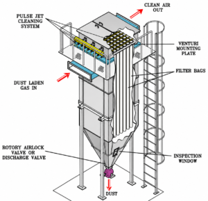
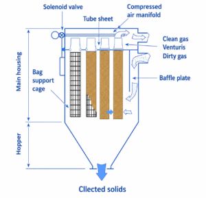
- Dust-laden air enters the collector through the inlet, often via a diffuser or baffle that reduces velocity and protects filter media.
- Coarse particles fall directly into the hopper by gravity; finer cement/ash particles are captured on the outside surface of fabric bags or pleated cartridges.
- Clean air passes through the filter media and exits through the clean-air plenum and exhaust stack.
- A dust cake builds on the filter surface, improving filtration but increasing pressure drop.
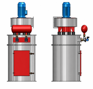
- A sequential timer actuates solenoid valves; short pulses of dry compressed air are injected through blow pipes, dislodging the dust cake into the hopper.
- Collected dust is discharged through a rotary airlock valve, slide gate, or screw conveyor, and is commonly returned to the silo or batching system.
Description
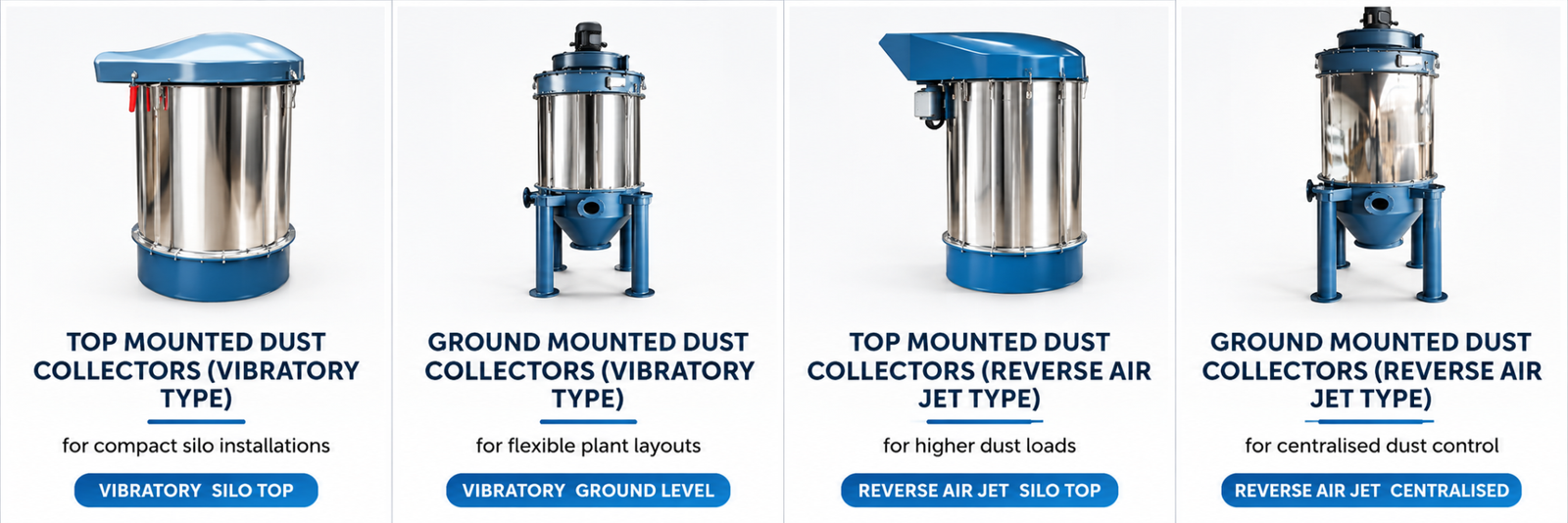
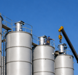
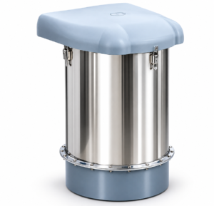
A top-mounted dust collector—also called a bin vent, silo vent filter, or silo-top baghouse—is installed directly on the roof of a cement, fly-ash, mineral-admixture, or filler silo. It vents displaced air during pneumatic silo filling and prevents dust emission at the silo vent.
Typical Specifications
Parameter | Typical range / specification |
Configuration | Silo-top bin vent, passive or fan-assisted pulse-jet collector |
Airflow | About 400–3,000 acfm for individual silo vents; larger units are available |
Filter media | Polyester spun-bond / needle felt, typically 7.7–7.8 oz/yd²; PTFE membrane or anti-static options for difficult dusts |
Filter type | Fabric bags or pleated cartridges |
Cleaning | Reverse pulse-jet compressed air, commonly 90–110 psig |
Filtration efficiency | 99% to 99.9%, depending on media and dust loading |
Typical air-to-cloth ratio | About 4:1 to 6:1 for cement dust in pulse-jet service |
Differential pressure | Commonly monitored at approximately 3–7 inches w.c.; some permits specify 2–6 inches w.c. |
Dust discharge | Gravity return to silo, rotary valve, or manual discharge |
Application | Single cement/fly-ash silo, filler silo, small weigh hopper |
Advantages
- No separate foundation or large ground area required.
- Short duct runs and lower ducting cost.
- Collected cement can often return directly to the same silo.
- Simple operation for individual silo venting.
Limitations
- Maintenance requires safe access at silo-top height.
- Limited capacity for multiple dust points.
- Replacement of bags/cartridges can be difficult in confined silo-top locations.
- Weather exposure requires protective enclosures, weather hoods, and corrosion-resistant construction.
Description
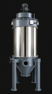
A ground-mounted dust collector is installed at grade level and connected by ducting to several emission sources—such as multiple silos, cement weigh hoppers, mixer charging points, and truck-loading hoppers. It is preferred where several dust points must be controlled by one larger, easily accessible unit.
Typical Specifications
Parameter | Typical range / specification |
Configuration | Central pulse-jet baghouse or cartridge collector at grade level |
Airflow | Commonly 3,000–12,000+ acfm, depending on number of suction points and simultaneous operation |
Filter type | Fabric bags or pleated cartridge elements |
Filter media | Polyester spun-bond / needle felt; anti-static or PTFE-treated media where required |
Example filtration area | A 36-cartridge unit may provide about 50–70 m²; larger baghouse systems can exceed 200 m² |
Example baghouse data | 30 bags, 8 in. × 78 in., 2,280 ft² filter area, 12,400 acfm, A/C ratio 5.3:1 |
Cleaning | Pulse-jet compressed-air cleaning; plant air around 95–110 psig is typical |
Blower | Centrifugal/radial-blade suction fan; examples include 5–15 HP depending on airflow |
Dust discharge | Hopper, rotary airlock, screw conveyor, or dust-return line |
Efficiency | 99%+ for cartridge units; 99.9% is commonly specified for high-efficiency baghouse installations |
Application | Multiple silos, weigh batchers, mixer charging, truck-loading points |
Advantages
- One collector can serve multiple silos and batching points.
- Easier inspection, bag/cartridge replacement, and hopper cleaning at ground level.
- Better suited to high airflow and high dust-loading plants.
- Lower working-at-height risk during routine maintenance.
Limitations
- Requires ducting, supports, dampers, and sometimes booster/extraction fans.
- Higher initial civil and structural work.
- Dust-return routing may be longer.
- Duct leakage, blockage, and condensation must be controlled.
Aspect | Top-mounted / bin vent | Ground-mounted central collector |
Location | Directly on silo roof | At grade level, connected by ducting |
Main use | Venting one silo during filling | Multiple dust points and higher total airflow |
Dust return | Usually direct to same silo | To selected silo, batcher, or disposal system |
Maintenance access | Height-access equipment often needed | Easier ground-level access |
Footprint | Minimal ground footprint | Requires foundation and ducting space |
Typical airflow | Lower to medium | Medium to high |
Best suited for | Single cement/fly-ash silo | Large RMC plants, multiple silos, mixer/loading dust control |
Maintenance complexity | Lower system complexity, higher access difficulty | More components, but simpler physical access |
Component | Common material | Purpose / standard relevance |
Collector casing, hopper, plenum | MS with epoxy/polyurethane painting; SS 304/316 for corrosive service | Structural strength and corrosion protection; stainless steel is preferred for coastal, humid, or chemically aggressive environments |
Filter bags | Polyester needle felt/spun-bond, typically 7.7–7.8 oz/yd² | Standard cement/fly-ash filtration; polyester is widely used below about 275°F |
Filter cartridges | Polyester spun-bond pleated media; anti-static or PTFE-treated options | Higher filter area in compact housings; anti-static media is offered for dust-control safety |
Cage / bag support | Galvanized steel or stainless steel | Maintains bag shape and prevents collapse during pulse cleaning |
Blow pipes, solenoid valves | MS/SS piping; aluminium or brass valve bodies | Compressed-air pulse cleaning |
Hopper and discharge valve | MS hopper with hardened/abrasion-resistant liner; cast-iron or SS rotary valve | Abrasion resistance and controlled dust discharge |
Ducting | MS spiral duct, galvanized steel, or SS where needed | Dust transport; design should maintain adequate transport velocity, commonly above about 18 m/s for fine dust systems |
Gaskets | EPDM, silicone, or neoprene | Air-tightness and weather sealing |
Structural supports | MS fabricated structure, hot-dip galvanized or painted | Support, vibration resistance, and corrosion protection |
Filter selection should consider dust temperature, abrasiveness, moisture, and electrical conductivity. Polyester is versatile for normal cement-dust service, while PTFE membrane, anti-static media, or higher-temperature media may be required for special applications.
- NFPA 654 — Prevention of fire and dust explosions from combustible particulate solids; relevant to dust-hazard analysis, collector location, dust removal, and ignition control.
- NFPA 68 — Explosion venting, applicable where combustible dust risk requires deflagration venting.
- NFPA 69 — Explosion prevention systems.
- EPA Method 9 / Method 22 — Visible-emissions/opacity checks; some concrete-plant permits limit visible emissions to no more than 30 seconds in any six-minute period.
- Air-permit requirements — Many jurisdictions require baghouses or central dust collectors for silos and weigh batchers, daily pressure-drop recording, and documented inspections.
- Manufacturer specifications — Airflow, cloth area, pressure drop, bag/cartridge dimensions, cleaning system, and fan data should be documented for the specific collector.
In India, the applicable compliance framework will also include the Air (Prevention and Control of Pollution) Act, 1981, CPCB/SPCB consent conditions, and site-specific emission norms. The mechanical design should follow the OEM data sheet and applicable structural, electrical, and safety codes.
Daily checks
- Record differential pressure across filters at least once per operating day; many permits require this during operation.
- Check for visible emissions at the exhaust stack.
- Verify compressed-air pressure, solenoid operation, and pulse-cleaning sequence.
- Inspect hopper discharge and ensure dust is not bridging or accumulating.
- Check silo high-level indicator, pressure-relief vent, and shut-off/warning devices; monthly testing is commonly required.
Weekly / monthly checks
- Inspect ducting, dampers, inlet diffusers, access doors, gaskets, and external casing for leakage, abrasion, or dust deposits.
- Inspect pulse-jet valves, diaphragms, blow pipes, and timer controller.
- Check fan bearings, belt tension where applicable, vibration, and motor current.
- Conduct and record a visual inspection of the collector and ductwork while the plant is operating; some permits require monthly records.
Periodic maintenance
- Replace damaged, blinded, or leaking bags/cartridges; keep a set of replacement filters and critical spares on site.
- Clean or replace pre-filters, inspect filter media for tears, moisture damage, and dust cake build-up.
- Calibrate or replace differential-pressure gauges at least annually, or as recommended by the manufacturer.
- Inspect rotary airlock clearance, hopper liners, and dust-return piping for wear.
- Conduct an up-close baghouse inspection at least annually, or more frequently if the OEM recommends it.
Suggested maintenance schedule
Frequency | Activity |
Every shift / daily | Differential pressure, compressed-air pressure, visible emissions, hopper discharge, abnormal noise/vibration |
Weekly | Pulse valves, timer sequence, duct joints, access doors, fan condition |
Monthly | Detailed external inspection, solenoid/diaphragm check, silo safety devices, record review |
Quarterly | Filter inspection, hopper cleaning, dust-return line inspection, fan bearing lubrication |
Annually | Complete internal inspection, gauge calibration, bag/cartridge replacement assessment, structural and corrosion inspection |
For a medium-capacity RMC plant with two cement/fly-ash silos, a cement weigh hopper, and a mixer/truck-loading point, a practical configuration is:
- Two top-mounted bin vents on cement and fly-ash silos, each rated for the silo filling airflow.
- One ground-mounted central pulse-jet cartridge collector for weigh hopper, mixer charging, and truck-loading extraction.
- Polyester spun-bond/needle-felt media, with PTFE membrane where very fine emission control is required.
- Differential-pressure gauge with alarms, pulse-jet timer, compressed-air dryer/filter, rotary airlock, and dust-return arrangement.
- Design filtration efficiency of at least 5%, with 99.9% preferred where permits or environmental conditions demand it.
This arrangement combines the simplicity of silo-top venting with the capacity and maintainability of a central ground-mounted collector.